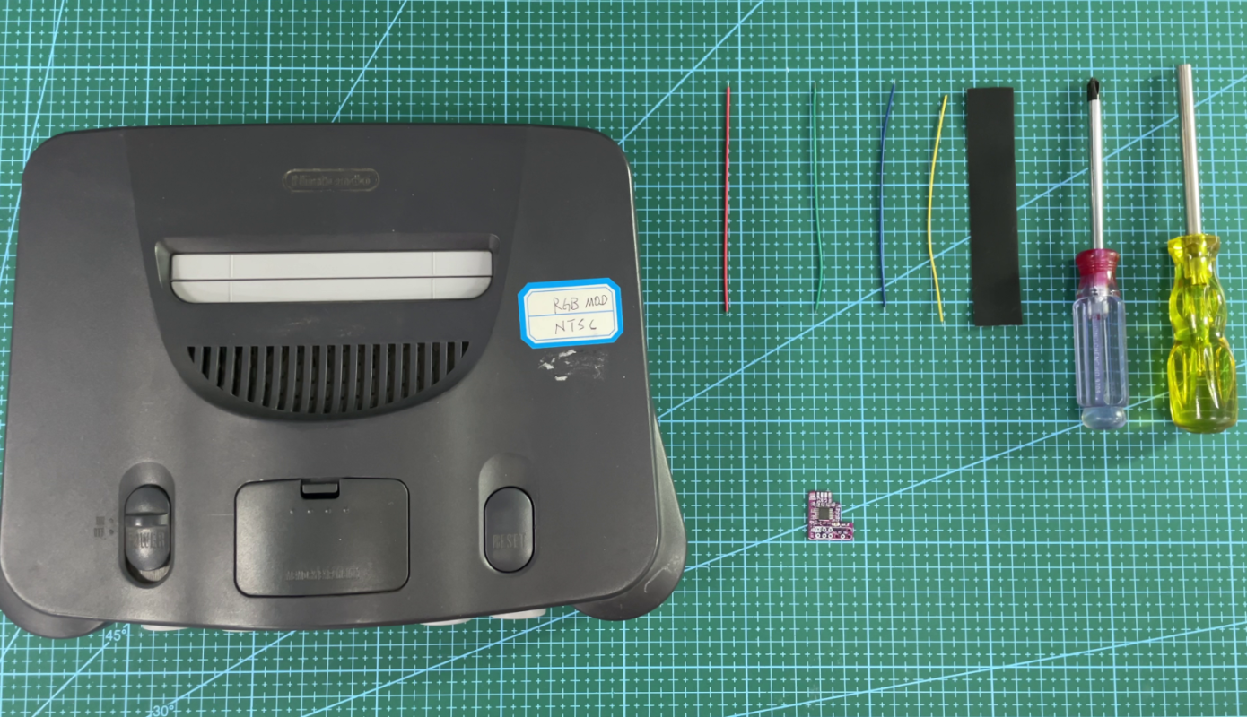
Tools required:
Phillips Screwdriver
4.5mm Game Security Bit
Four electronic wires
A piece of insulating tape
N64 RGB mod
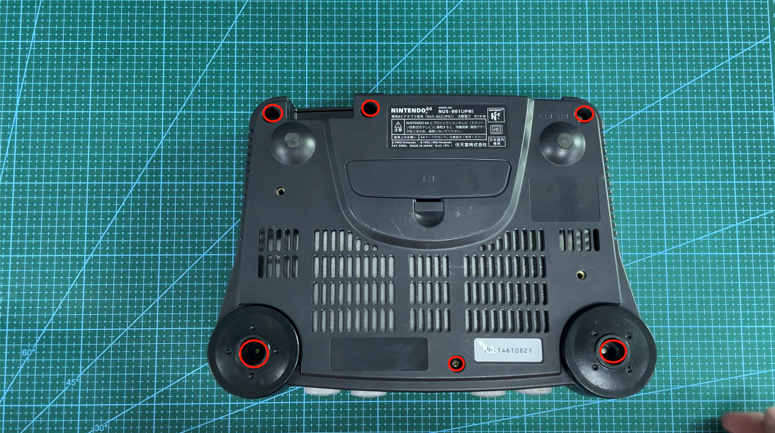
Step 1
Using a 4.5mm game security bit, remove the 6 screws from the bottom of the
N64
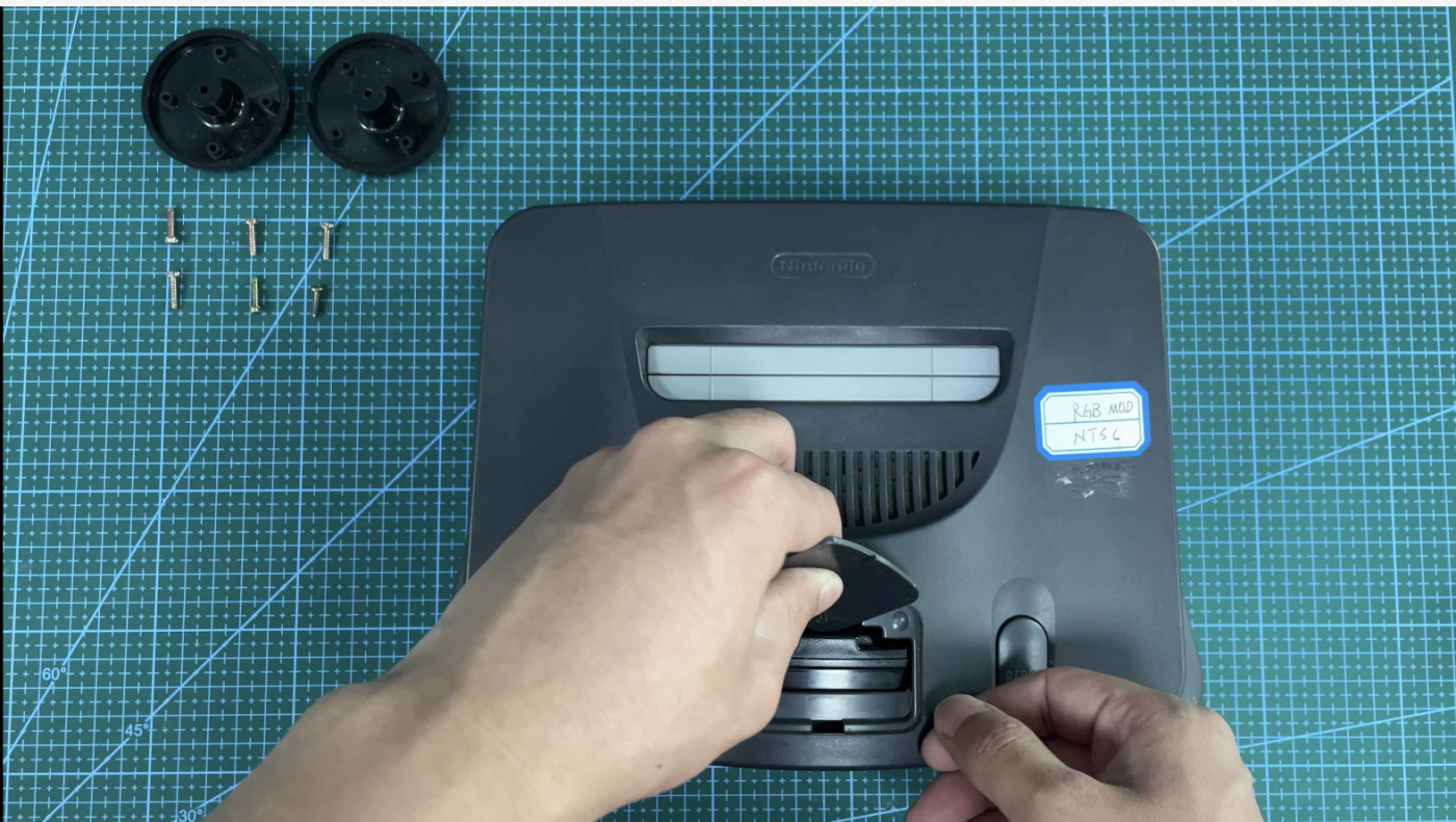
Step 2
Begin disassembly by removing the jumper/expansion pak from the N64 and remove the top half of the N64 shell.
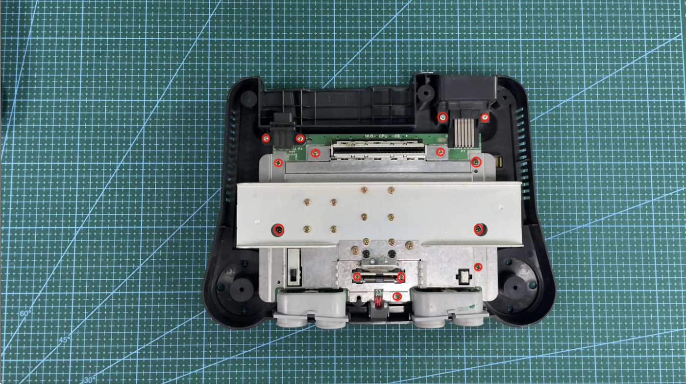
Step 3
Remove the 14 phillips screws that secure the N64 PCB and remove the PCB.
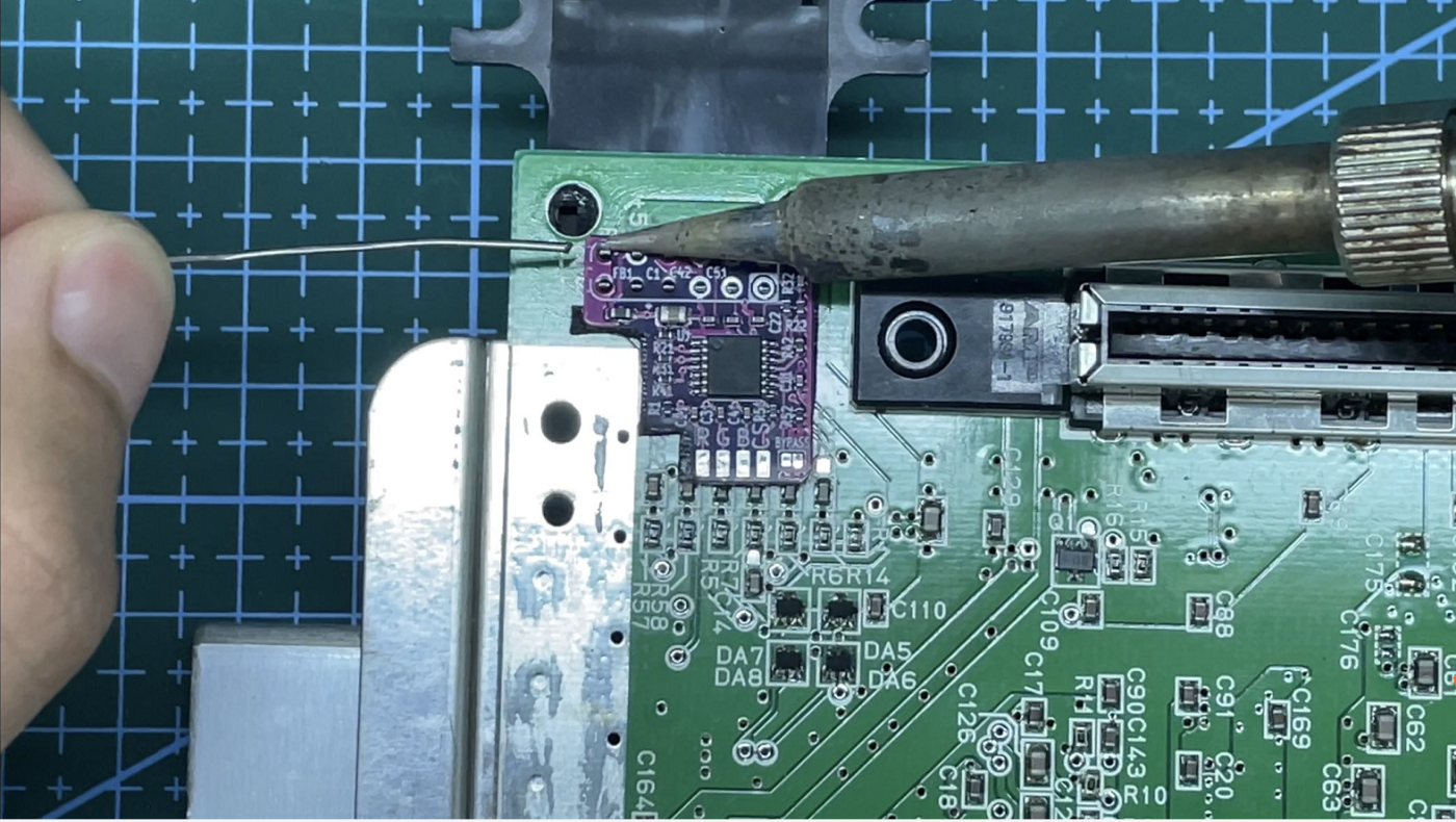
Step 4
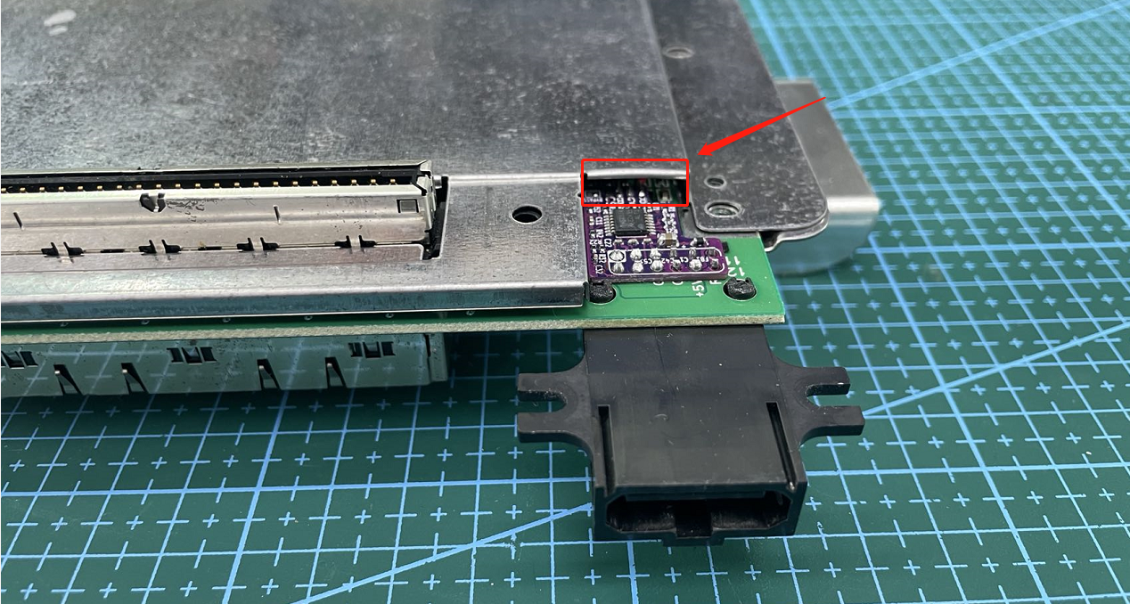
Place the N64RGB mod over the multi-out pins and solder into position.
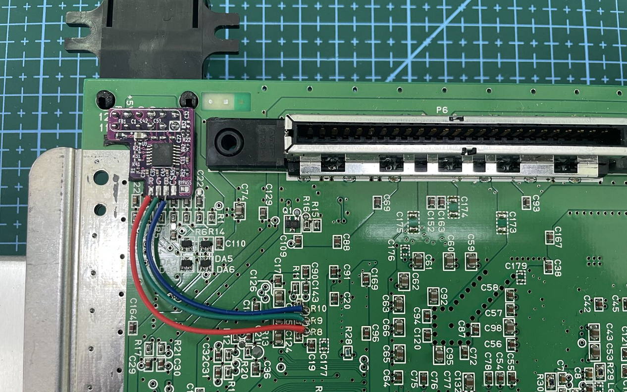
Step 5
If using supplied ribbon cable. Bend ribbon cable at a 90° angle and remove the
excess. Solder into position. R10 = Blue, R9 = Green, and R8 = Red.
Step 6
Early N64’s drive and buffer C-Sync to the multi-out. If Q1, R16, R15, and C109
are present and you have an appropriate C-Sync cable, The installation can be completed directly, skip the following steps.
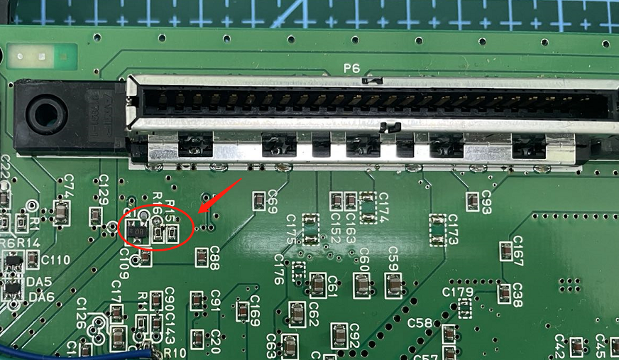
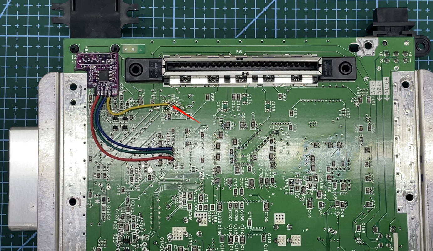
Step 7
For N64’s with the C-Sync circuitry missing, Solder into position,R16=CS
Step 8
bend up the metal flap of the bottom RF shield in order to prevent shorting